Table of Contents
- Since
- 0.9.4
Part of Topology package and Shapes package
This part of the manual describes how to represent combinatorial surfaces, generally embedded in \(\mathbb{R}^3\). The underlying combinatorial topological structure is the classical half-edge data structure (or doubly connected cell list). We also provide a triangulated surface representation that is based on an half-edge data structure. A more general polygonal surface is provided and is also based on the same half-edge data structure. In the latter case, faces of the surface can be arbitrary simple polygons.
The following programs are related to this documentation:
- See also
- testHalfEdgeDataStructure.cpp, testTriangulatedSurface.cpp, viewMarchingCubes.cpp, viewPolygonalMarchingCubes.cpp
The half-edge data structure
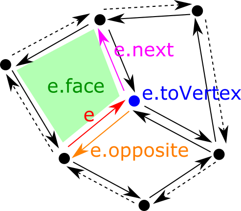
A half-edge data structure is a way to represent the topology of a combinatorial surface. A combinatoirial surface is a union of vertices, edges (a curve bordered by two vertices), faces (a piece of surface bordered by a sequence of edges). They are often called 0-cells, 1-cells and 2-cells respectively. The half-edge data structure describes which cells are connected to each other. Its principle is to associate two half-edges to each edge. Once this is done, it is easy to tie cells together by simply indicating for each half-edge:
- its next half-edge (along its face)
- its opposite half-edge (along the edge, that the half-edge associated to the neighboring face)
- its associated face
- its associated vertex (here, we choose the "to" vertex if the half-edge is seen as an arc)
- its associated edge
The classical half-edge data structure is implemented in the class HalfEdgeDataStructure.
- Note
- Large parts of this class are taken from https://github.com/yig/halfedge, written by Yotam Gingold.
Creating a half-edge data structure
For now, you only have methods to create a half-edge data structure from a set of triangles and edges. For instance, the following code builds a half-edge data structure representing two triangles tied along one edge:
All elements within the half-edge data structure are numbered, starting from 0. Furthermore, the indices of vertices and triangles are the same as the one given at initialization.
So, for instance, in the code above, triangle 0 is incident to vertices 0, 1, 2 and triangle 1 is incident to vertices 2, 1, 3.
- Note
- Unordered edges may also be numbered according to your preference, but you need to call the other HalfEdgeDataStructure::build method, which takes as input triangles and edges, not only triangles. In this case, this other method builds a half-edge structure that keeps both the numbering of triangles and edges.
Elementary operations
Since half-edges are the basis of the structure, you have operations to get a half-edge from an arc (i.e. a couple of vertices), or from neighboring vertices or faces:
- HalfEdgeDataStructure::halfEdgeIndexFromArc : given an arc or two vertices, returns the corresponding half-edge index (logarithmic cost in the number of half-edges)
- HalfEdgeDataStructure::halfEdgeIndexFromVertexIndex, HalfEdgeDataStructure::halfEdgeIndexFromFaceIndex, HalfEdgeDataStructure::halfEdgeIndexFromEdgeIndex: returns the index of a half-edge that borders the given vertex, face or edge (constant time operation)
- HalfEdgeDataStructure::halfEdge : given a half-edge index, returns the half-edge itself.
Then, each half-edge can give you its associated vertex, face, edge, opposite and next half-edge:
- HalfEdgeDataStructure::HalfEdge::toVertex : the end vertex of this half-edge as an index into the vertex array.
- HalfEdgeDataStructure::HalfEdge::face : index of the associated face into the face array.
- HalfEdgeDataStructure::HalfEdge::edge : index of the associated edge into the edge array.
- HalfEdgeDataStructure::HalfEdge::opposite : index of the opposite half-edge into the half-edge array.
- HalfEdgeDataStructure::HalfEdge::next index of the next half-edge along the face into the half-edge array.
Finally a half-edge data structure can give you all the necessary neighboring information, and can also list the vertices and arcs that lie on the boundary of the data structure:
- HalfEdgeDataStructure::neighboringVertices, HalfEdgeDataStructure::getNeighboringVertices : returns the sequence of vertices that are neighbors to the given vertex. The order of neighbors has meaning and corresponds to the order given at the initialization per triangle.
- HalfEdgeDataStructure::neighboringFaces, HalfEdgeDataStructure::getNeighboringFaces : returns the sequence of faces that are incident to the given vertex. The order of neighbors has meaning and corresponds to the order given at the initialization per triangle.
- HalfEdgeDataStructure::boundaryVertices, HalfEdgeDataStructure::boundaryHalfEdgeIndices, HalfEdgeDataStructure::boundaryArcs : returns the vertices and/or arcs lying on the boundary of the combinatorial surface (in no particular order).
Details about internal representation
It is worthy to note the following elements in this representation:
- half-edges, vertices, edges and faces are numbered consecutively from 0.
- vertices and faces (here triangles) keep their numbering given at initialization.
- given a vertex index, an edge index, or a face index, you can get an half-edge incident to it in constant time (stored as a vector).
- given an arc (i.e. a couple of vertices), you can get the corresponding half-edge in logarithmic time (stored as a map).
Modifying operations: flip, split, merge
Since 1.1, there is a limited support for classical flip, split and merge operations. For now, it is limited to triangulated half-edge date structures, i.e. a face is bordered by three half-edges.
- HalfEdgeDataStructure::isFlippable tells if some edge is flippable, i.e. it is bordered by two valid triangles;
- HalfEdgeDataStructure::flip flips the given edge if the edge is flippable, so that the edge now connects the two other vertices of the bordering two triangles;
- HalfEdgeDataStructure::split splits the given edge if the edge is flippable, i.e. creates a new vertex on this edge and two new triangles;
- HalfEdgeDataStructure::isMergeable tells if some edge is mergeable, i.e. (1) it is bordered by two triangles, (2) there is no boundary vertex in the two triangles bordering the edge;
- HalfEdgeDataStructure::merge merges the given edge and the two bordering triangles, leaving only one vertex and two edges, only if the edge is mergeable.
There is also a method HalfEdgeDataStructure::isValid that performs a lot of checks on the validity of the data structure.
- Note
- Methods HalfEdgeDataStructure::isFlippable and HalfEdgeDataStructure::isMergeable has \( O(1) \) time complexity. Methods HalfEdgeDataStructure::flip, HalfEdgeDataStructure::split and HalfEdgeDataStructure::merge have \( O(1) \) time complexity when optimization parameter
update_arc2indexisfalse, and \( O(\log n) \) time complexity otherwise, where \( n \) stands for the number of half-edges.
A triangulated surface data structure
A triangulated surface is a two-dimensional simplicial complex, with a piecewise linear geometry. We use the half-edge data structure to represent its topology and its geometry is simply given by precising coordinates for each vertex. The class TriangulatedSurface represents this geometric object. You may also associate other information to each vertex of the surface, through TriangulatedSurface::VertexPropertyMap objects.
A triangulated surface is a model of graph (concepts::CUndirectedSimpleGraph) so you may use graph algorithms to traverse it (see Basic graph definitions and concepts).
Building a triangulated surface
A triangulated surface is parameterized by the type that represents the coordinates of each vertex. Then you simply add vertices by specifying their coordinates, and triangles by giving the indices of the three vertices counterclockwise. Once this is done, you must call TriangulatedSurface::build to finish the construction. The following code creates a tetrahedron.
Note that the topology that ties triangles together is built when calling TriangulatedSurface::build. If the topology is valid, it returns true. This method may return false for instance in the following cases:
- three triangles sharing an edge,
- number of vertices given by triangles does not match the number of vertex coordinates,
- butterfly neighborhoods in the triangulation.
Main topological operations
As a model of graph (more precisely concepts::CUndirectedSimpleGraph), you can get neighbors of vertices, degree and some other operations, as well as iterators for visiting vertices. As a combinatorial surfaces you have a lot of other operations to navigate onto the triangulated surface:
- vertex to vertices: you can get the neighboring vertices with TriangulatedSurface::writeNeighbors.
- vertex to arcs: you can get ingoing and outgoing arcs with TriangulatedSurface::inArcs and TriangulatedSurface::outArcs. The order is significant.
- vertex to faces: you can get the faces incident to the given vertex with TriangulatedSurface::facesAroundVertex.
- arc to vertices: you can get the head and the tail of an arc with TriangulatedSurface::head and TriangulatedSurface::tail.
- arc to opposite arc: with TriangulatedSurface::opposite.
- arc to face: you can get the only face incident to the given arc with TriangulatedSurface::faceAroundArc (may be invalid) or as a sequence of zero or one face with TriangulatedSurface::facesAroundArc.
- face to vertices: you can get the sequence of vertices incident to a given face with TriangulatedSurface::verticesAroundFace, in the same order as the sequence of incident arcs along the face. Here, it returns three vertices.
- face to arcs: you can get the sequence of 3 arcs incident to a given face with TriangulatedSurface::arcsAroundFace, in the same order as the sequence of incident arcs along the face.
Furthermore you can enumerate all the vertices, arcs and faces with TriangulatedSurface::allVertices, TriangulatedSurface::allArcs, TriangulatedSurface::allFaces.
Boundary of triangulated surface
Some of the edges of the triangulation may not be shared by two triangles, but only one. This set of edges, which may be organized in sequences, forms the boundary of the surface, which may be connected or disconnected. You have some operations to access to the boundary of the surface:
- TriangulatedSurface::isVertexBoundary tells if some vertex lies on the boundary.
- TriangulatedSurface::isArcBoundary tells if an arc is a boundary arc (its opposite is then not in the boundary)
- TriangulatedSurface::allBoundaryArcs returns the set of all arcs (oriented edges) lying on the boundary of the surface (in no particular order).
- TriangulatedSurface::allBoundaryVertices returns the set of vertices lying on the boundary of the surface (in no particular order).
Helpers to convert triangulated surfaces from/to mesh
File MeshHelpers.h provides two methods to convert a Mesh into a TriangulatedSurface and conversely.
- MeshHelpers::mesh2TriangulatedSurface builds a triangulated surface (class TriangulatedSurface) from an arbitrary mesh (class Mesh). Since a mesh may have non triangular faces, they are then triangulated naively (triangles (0,1,2), (0,2,3), (0,3,4), etc).
- MeshHelpers::triangulatedSurface2Mesh Builds a mesh (class Mesh) from a triangulated surface (class TriangulatedSurface). Note that the mesh looses the topology of the triangulated surface, since it is essentially a soup of triangles. It is useful for display or for export to OBJ format for instance.
- MeshHelpers::digitalSurface2DualTriangulatedSurface builds a triangulated surface (class TriangulatedSurface) from the dual graph of a digital surface (class DigitalSurface). It is for instance useful for building an isosurface.
You may have a look at example shapes/viewMarchingCubes.cpp to see an example of using MeshHelpers::digitalSurface2DualTriangulatedSurface and MeshHelpers::triangulatedSurface2Mesh.
Geometrical operations
The class TriangulatedSurface just come with a way to get/set the position of each vertex:
- TriangulatedSurface::position : setter/getter of position given a vertex index.
Associating data to vertices, edges, faces
The easiest way to associate data to vertices, edges or faces is to create a relevant TriangulatedSurface::IndexedPropertyMap. In fact, this is the mechanism used by the class TriangulatedSurface to store positions. The lines below show how to build a map associated an integer to each face:
Any TriangulatedSurface::IndexedPropertyMap is in fact a vector of value, the size of which depends on the number of vertices / edges / face. We exploit the fact that vertices, edges and faces are all numbered consecutively starting from 0. The following methods returns property maps:
- TriangulatedSurface::makeVertexMap<T> : creates a map associating a value of type T to each vertex.
- TriangulatedSurface::makeEdgeMap<T> : creates a map associating a value of type T to each edge.
- TriangulatedSurface::makeFaceMap<T> : creates a map associating a value of type T to each face.
- TriangulatedSurface::positions : returns an alias to the map giving the position of each vertex.
Triangulated surface I/O and visualization
You have methods to export a triangulated surface as an OBJ file: MeshHelpers::exportOBJ or the more complete MeshHelpers::exportOBJwithFaceNormalAndColor.
In its present form, class TriangulatedSurface does not provide any visualization methods. However it is simpler to convert a TriangulatedSurface to/from a Mesh for I/O or for visualization (see Helpers to convert triangulated surfaces from/to mesh).
You may input or output a Mesh as an OFF/OFS/OBJ file, see Mesh IO. More precisely, class MeshWriter allows you to output a Mesh as an OFF/OFS/OBJ file while class MeshReader can input an OFF/OFS file into a Mesh.
For visualization, you may also directly stream a Mesh into a PolyscopeViewer.
Modifying operations: flip, split, merge
Since 1.1, there is a limited support for classical flip, split and merge operations for triangulated surfaces.
- TriangulatedSurface::isFlippable tells if some edge is flippable, i.e. it is bordered by two valid triangles;
- TriangulatedSurface::flip flips the given edge if the edge is flippable, so that the edge now connects the two other vertices of the bordering two triangles;
- TriangulatedSurface::split splits the given edge if the edge is flippable, i.e. creates a new vertex on this edge and two new triangles;
- TriangulatedSurface::isMergeable tells if some edge is mergeable, i.e. (1) it is bordered by two triangles, (2) there is no boundary vertex in the two triangles bordering the edge;
- TriangulatedSurface::merge merges the given edge and the two bordering triangles, leaving only one vertex and two edges, only if the edge is mergeable.
- Note
- These methods only checks that these operations are topologically valid. They do not check if the geometry of the resulting surface is valid, for instance that there is no self-intersections.
- Methods TriangulatedSurface::isFlippable, TriangulatedSurface::isMergeable, TriangulatedSurface::flip, TriangulatedSurface::split and TriangulatedSurface::merge have all \( O(1) \) time complexity.
A polygonal surface data structure
A polygonal surface is a two-dimensional simplicial complex, with a piecewise linear geometry per face. Contrary to class TriangulatedSurface, faces are not restricted to triangles but may be arbitrary simple polygons. We use the half-edge data structure to represent its topology and its geometry is simply given by precising coordinates for each vertex. The class PolygonalSurface represents this geometric object. You may also associate other information to each vertex of the surface, through PolygonalSurface::VertexPropertyMap objects.
A polygonal surface is a model of graph (concepts::CUndirectedSimpleGraph) so you may use graph algorithms to traverse it (see Basic graph definitions and concepts).
Building a polygonal surface
A polygonal surface is parameterized by the type that represents the coordinates of each vertex. Then you simply add vertices by specifying their coordinates, and triangles by giving the indices of the three vertices counterclockwise. Once this is done, you must call PolygonalSurface::build to finish the construction. The following code creates a pyramid.
Note that the topology that ties faces together is built when calling PolygonalSurface::build. If the topology is valid, it returns true. This method may return false for instance in the following cases:
- three faces sharing an edge,
- number of vertices given by faces does not match the number of vertex coordinates,
- butterfly neighborhoods in the triangulation.
Main topological operations
As a model of graph (more precisely concepts::CUndirectedSimpleGraph), you can get neighbors of vertices, degree and some other operations, as well as iterators for visiting vertices. As a combinatorial surfaces you have a lot of other operations to navigate onto the polygonal surface:
- vertex to vertices: you can get the neighboring vertices with PolygonalSurface::writeNeighbors.
- vertex to arcs: you can get ingoing and outgoing arcs with PolygonalSurface::inArcs and PolygonalSurface::outArcs. The order is significant.
- vertex to faces: you can get the faces incident to the given vertex with PolygonalSurface::facesAroundVertex.
- arc to vertices: you can get the head and the tail of an arc with PolygonalSurface::head and PolygonalSurface::tail.
- arc to opposite arc: with PolygonalSurface::opposite.
- arc to face: you can get the only face incident to the given arc with PolygonalSurface::faceAroundArc (may be invalid) or as a sequence of zero or one face with PolygonalSurface::facesAroundArc.
- face to vertices: you can get the sequence of vertices incident to a given face with PolygonalSurface::verticesAroundFace, in the same order as the sequence of incident arcs along the face. It is thus the sequence of vertices representing the polygonal face.
- face to arcs: you can get the sequence of arcs incident to a given face with PolygonalSurface::arcsAroundFace, in the same order as the sequence of incident arcs along the face.
Furthermore you can enumerate all the vertices, arcs and faces with PolygonalSurface::allVertices, PolygonalSurface::allArcs, PolygonalSurface::allFaces.
Boundary of polygonal surface
Some of the edges of the combinatorial surface may not be shared by two triangles, but only one. This set of edges, which may be organized in sequences, forms the boundary of the surface, which may be connected or disconnected. You have some operations to access to the boundary of the surface:
- PolygonalSurface::isVertexBoundary tells if some vertex lies on the boundary.
- PolygonalSurface::isArcBoundary tells if an arc is a boundary arc (its opposite is then not in the boundary)
- PolygonalSurface::allBoundaryArcs returns the set of all arcs (oriented edges) lying on the boundary of the surface (in no particular order).
- PolygonalSurface::allBoundaryVertices returns the set of vertices lying on the boundary of the surface (in no particular order).
Helpers to convert polygonal surfaces from/to mesh
File MeshHelpers.h provides two methods to convert a Mesh into a PolygonalSurface and conversely.
- MeshHelpers::mesh2PolygonalSurface builds a polygonal surface (class PolygonalSurface) from an arbitrary mesh (class Mesh).
- MeshHelpers::polygonalSurface2TriangulatedSurface builds a polygonal surface from a triangulated surface (faces are triangulated according to parameters).
- MeshHelpers::polygonalSurface2Mesh builds a mesh (class Mesh) from a polygonal surface (class PolygonalSurface). Note that the mesh looses the topology of the polygonal surface, since it is essentially a soup of triangles. It is useful for display or for export to OBJ format for instance.
- MeshHelpers::digitalSurface2PrimalPolygonalSurface builds a polygonal surface (class PolygonalSurface) from the primal graph of a 2-dimensional digital surface in K^3 (class DigitalSurface).
- MeshHelpers::digitalSurface2DualPolygonalSurface builds a polygonal surface (class PolygonalSurface) from the dual graph of a digital surface (class DigitalSurface). It is for instance useful for building an isosurface.
You may have a look at example shapes/viewPolygonalMarchingCubes.cpp to see an example of using MeshHelpers::digitalSurface2DualPolygonalSurface and MeshHelpers::polygonalSurface2Mesh.
Geometrical operations
The class PolygonalSurface juste come with a way to get/set the position of each vertex:
- PolygonalSurface::position : setter/getter of position given a vertex index.
Associating data to vertices, edges, faces
The easiest way to associate data to vertices, edges or faces is to create a relevant PolygonalSurface::IndexedPropertyMap. In fact, this is the mechanism used by the class PolygonalSurface to store positions. The lines below show how to build a map associating an integer to each face:
Any PolygonalSurface::IndexedPropertyMap is in fact a vector of value, the size of which depends on the number of vertices / edges / face. We exploit the fact that vertices, edges and faces are all numbered consecutively starting from 0. The following methods returns property maps:
- PolygonalSurface::makeVertexMap<T> : creates a map associating a value of type T to each vertex.
- PolygonalSurface::makeEdgeMap<T> : creates a map associating a value of type T to each edge.
- PolygonalSurface::makeFaceMap<T> : creates a map associating a value of type T to each face.
- PolygonalSurface::positions : returns an alias to the map giving the position of each vertex.
Polygonal surface I/O and visualization
You have methods to export a polygonal surface as an OBJ file: MeshHelpers::exportOBJ or the more complete MeshHelpers::exportOBJwithFaceNormalAndColor.
In its present form, class PolygonalSurface does not provide any visualization methods. However it is simpler to convert a PolygonalSurface to/from a Mesh for I/O or for visualization (see Helpers to convert polygonal surfaces from/to mesh).
You may input or output a Mesh as an OFF/OFS/OBJ file, see Mesh IO. More precisely, class MeshWriter allows you to output a Mesh as an OFF/OFS/OBJ file while class MeshReader can input an OFF/OFS file into a Mesh.
For visualization, you may also directly stream a Mesh into a PolyscopeViewer.